2.4GHz
This meant we could pretty well mix and match between different brands and we paired our transmitter and receiver by fitting a matched pair of crystals which told our equipment to operate on a numbered 10khz channel within the allocated 35MHz frequency band. This standard has proved remarkably durable and I am still using receivers bought back in 1987 and, although they look big and clunky by today's standards, they continue to operate perfectly well.
Then rumours started about efforts to harness the 2.4GHz WiFi technology for radio control of models. Since this technology was originally designed for short range communication between computers in buildings, it perhaps wasn't an obvious choice and indeed many pundits (including some established manufacturers of r/c equipment) queued up to declare that it would never work and/or would be illegal.
When the Spektrum system launched, the modelling world had to sit up and take notice. Here was a system that promised to do away with the need for frequency control, waiting for your turn with the frequency peg and the ever-present risk of somebody turning up, switching on and shooting down your latest model. Many other claims were made too but at this stage there was no way of separating the hype from the reality.
There were a few teething troubles but eventually the criticisms gave way to enthusiasm about the new system and, one by one, the established manufacturers realised that this was a tide they couldn't resist and, whilst some licenced in the 2.4GHz technology, most set about producing their own variation on the theme. A major downside of this is that almost all the 2.4GHz systems on the market today are incompatible, i.e. receivers must be of the same make as the transmitter or transmitter module. The good thing though is that all systems operating on the 2.4GHz band are required to operate without mutual interference and, so far at least, they do indeed seem to do so.
For me, the main promise of the new technology was the claimed improvement in interference rejection. Ever since I started building higher power electric models (i.e. more than 8-cell NiCd or 3-Cell LiPo batteries), electrical interference had become a significant issue and I had several scale models which required the aerial to be strung outside the model in order to get satisfactory range performance. Also, I wanted to eliminate the nuisance of separate receiver batteries in order to capitalise fully on the 'always ready to go' nature of LiPo batteries, but found in some cases that fitting a uBEC instead of a receiver battery again generated interference problems. Strange how little one reads about these issues in the modelling magazines!?
Whilst I was happy, even eager, to move on from 35MHz to 2.4GHz, I was equally determined not to give up my Multiplex Profi 3030 transmitter. I have become well used to its programming method and its 99 model memory capacity means that I can dedicate a separate memory to each and every model, which I find really useful. So I waited for Multiplex to bring out their 2.4GHz offering. And I waited.... and waited.....
I was about to give up waiting when Multiplex finally announced their M-Link system, due to be available from July 2009. It looked pretty good on paper but, as more information became available, I was concerned about the receiver prices - I have a lot of models to convert! So I had another look at the alternative - third party modules which could be fitted into my transmitter. By this time the Jeti system had appeared and seemed to offer very good functionality for its price and, as July 2009 approached and the Multiplex receiver prices began to firm up, I began to feel increasingly uncomfortable about committing to the Multiplex solution and eventually plucked up the courage to phone John Emms of Puffin Models and bought into the Jeti route.
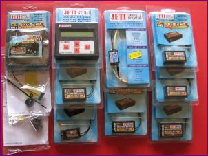
Transmitter Conversion Jeti do a number of modules designed to plug into different transmitters in place of the original 35MHz module. Unfortunately, no such packaged, plug-in unit was available for the Multiplex 3030 (as I write, a module for the Profi has been announced, but I have no details on it) . However, the 'TU' module is a bare card designed to be fitted to practically any transmitter, even if it has to be mounted externally, picking up its power and the PPM signal from the trainer socket.
In the case of the 3030 though, there is plenty of room in the module bay and a length of cable can be used to plug into the module connector to pick up the power and PPM signal inputs that the module needs. Take care though - this connector can be put on either way round, and only one way is right!
The System in Use
Range testing is done by setting the transmitter in range test mode, either via the Jetibox or by using the bind plug. Then the instruction is to "place the model and transmitter at least 80cm high above the ground", however no antigravity device is provided so the model was placed on the ground and I carried the transmitter in the normal way as I set off on my 50m walk. The Jetibox displays the received signal strength so there is no need to waggle servos - just keep on walking and watch the signal strength drop off from 9 to 8 to 7 etc. The different types of receiver do have some differences in sensitivity and I did see lower signal strengths with a model flat on the grass than with those which stood on their wheels, but I have now put 13 receivers through this test and all have passed, without the need resort to levitation. For the first few, I did have somebody hold the model whilst I ran the motor up to check for any interference, but the signal strength remained completely steady indicating that the system does indeed seem pretty impervious to electrical noise from motors, ESCs and uBECs.
So - no more external aerials and all models are now flying on BEC or uBEC so no receiver batteries to charge up. And no glitches. Brilliant!
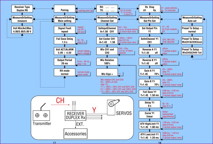
Receiver Settings
So far, as part of the installation process, I am trying to make sure that I remember to configure the failsafe and set the output period of the receiver to follow the transmitter frame rate. Apart from that, the only facilities I have used have been the delay and travel limit which I use on flap servos to reduce the risk of driving them beyond their endstops and to make the flaps change position over a period of a few seconds after flipping the switch on the Tx. Both of these features are of course set on the Tx as well but maybe setting them up on the Rx gives a bit more protection?
Telemetry
Just to add to the fun, Jeti are progressively introducing a range of onboard sensors which simply plug into the receiver and relay data over the downlink for display on the Jetibox. At the time of writing (October 2009) there are sensors for measuring RPM, Temperature, Battery voltage/current/used capacity, and a Vario. There may well be others by the time you read this.
So far, I have only tried the voltage/current/capacity measurement device. This can be used on the ground for static tests instead of a watt meter or clamp meter. But then you can continue to take readings in flight. Not having recruited my co-pilot yet, all I have used this for is to note the battery capacity used at the end of the flight to assist in setting my flight timer. There are though several other experiments I want to do. For example, my Sealand will fly for up to half an hour on a 3700mah 3s battery, and I would love to know just how much power it needs to maintain cruising flight. at the other end of the scale, I wonder what the maximum current draw of my aerobatic models is in flight compared to that measured on the ground.
Conclusion
|
||
 When I got into radio controlled model flying in 1987, there were a few people still flying on the original 27MHz system but basically all model flying in the UK was on 35MHz, using an FM/PPM modulation system which had been adopted by all the main r/c equipment manufacturers.
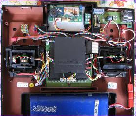
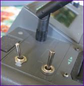
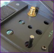 Then it is a case of mounting the antenna. I was keen to avoid making any permanent modifications to the transmitter case, at least until I had built up some confidence in the system, so opted to mount the antenna in one of the spare switch positions. When I first did this I found that there wasn't quite enough free thread left on the socket to enable the antenna base to be screwed fully home before it encountered the socket retaining nut. The secret here is not to fit the retaining nut on the top of the removeable switch plate but instead, remove the switch plate, and tighten the nut against the inner transmitter skin before re-fitting the switch plate. This freed up a few more millimeters of thread which was enough to make sure that the antenna made good contact with its socket.
 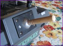 One of the selling points of the Jeti system is its full duplex operation, providing continuous air-to-ground telemetry. The Multiplex M-Link system offers this too but one of the drawbacks is that, when retro-fitted to the Profi 3030, the data received over the downlink cannot be displayed on the transmitter. Because the Jeti system is designed from the outset to be retro-fitted to various transmitters, the downlink data is displayed on a separate 'Jetibox'.
 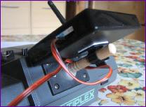 This neat device consists of a display and four buttons and, as well as displaying telemetry data, provides an interface to manage the astonishing array of features and options built into the receivers - more of that later. So, the last act in the transmitter conversion is to route the connecting lead out through the wall of the Tx case (The Profi has a handy blanking plate opposite the trainer socket) and work out a way of mounting the Jetibox to the transmitter. As you can see, I fitted a short length of dowel into the now redundant 35MHz antenna socket, and the Jetibox clips securely onto this.
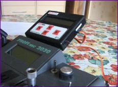 So, the next step was to plug the binding plug into a receiver, connect a battery and a servo, then switch on the Tx. A happy beep from the Tx module indicated that the Tx and Rx had recognised each other and a waggle of the sticks showed that they were indeed communicating - magic!
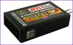 My electric models were converted and test flown progressively over the next couple of months, using a selection of receivers: the R4, R5, R6 and R8. I started with the models which were known to be interference - prone. Of course, the 2.4GHz receivers all have two short aerials and arranging them at roughly 90 degrees within the fuselage was no problem, usually involving nothing more than a couple of pieces of masking tape.